![ASD_icon_4c.png]](https://knowledgebase.agrispraydrones.com/hs-fs/hubfs/ASD_icon_4c.png?width=50&height=50&name=ASD_icon_4c.png)
Standard Operating Procedure (SOP)Agricultural UAS Repair Verification Checklist — Technician
Field Reference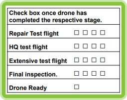
SOP Number: US.01.02.002
Version Number: 1.0.0
Effective Date: [03/17/2026]
Last Revised: [09/09/2026]
This is a simplified working copy. For full item descriptions, torque specifications, safety considerations, troubleshooting procedures, and regulatory references, refer to the master document: FAA Repair SOP ASD.001.01.04
Checklist Instructions
- [✓] — Repaired, inspected, and/or tested — satisfactory condition.
- [N/A] — Not part of this repair; not serviced.
- [Note] — Deficient; not corrected; requires further action (document in Notes).
All replacement parts must be genuine OEM or ASD-approved equivalent.
8.0 Pre-Check
|
Date and time started: |
|
|
Customer name: |
|
|
Serial number: |
|
|
Shopify order #: |
|
|
HubSpot #: |
8.1 Section 1: Chassis
|
# |
Item |
✓ |
N/A |
Notes / Parts Used |
|
1.1 |
Landing Gear |
|||
|
1.2 |
Airframe / Center Body |
|||
|
1.3 |
Arm Carbon Tubes |
|||
|
1.4 |
Arm Mounting Brackets |
|||
|
1.4.1 |
Main controller mounting bracket. |
|||
|
1.5 |
Vibration Dampeners / Isolators |
|||
|
1.6 |
Screws & Fasteners (Chassis) |
|||
|
1.7 |
Additional Chassis Repairs: |
Chassis Section — Technician Initials: _______ Date: _______
8.2 Section 2: Propulsion System
|
# |
Item |
✓ |
N/A |
Notes / Parts Used |
|
2.1 |
Propellers (56" / 63") |
|||
|
2.1.5 |
Prop Clamp (remove clamp visual inspection) |
|||
|
2.2 |
Motors |
|||
|
2.3 |
Electronic Speed Controllers (ESCs) |
|||
|
2.4 |
Screws & Fasteners (Propulsion) |
|||
|
2.5 |
Additional Propulsion Repairs: |
Propulsion Section — Technician Initials: _______ Date: _______
8.3 Section 3: Electrical Systems
|
# |
Item |
✓ |
N/A |
Notes / Parts Used |
|
3.1 |
Battery Terminals & Connectors |
|||
|
Battery guide rails, fitment and style. |
||||
|
3.2 |
Battery Condition |
Cycle count: |
||
|
3.3 |
Chassis Wiring & Harnesses |
|||
|
3.4 |
FPV / Operational Camera |
|||
|
3.5 |
Lidar |
|||
|
3.6 |
Obstacle Avoidance Systems |
|||
|
3.7 |
RTK Positioning System |
|||
|
3.8 |
Remote Controller |
|||
|
3.9 |
Antennas (Aircraft) |
|||
|
3.11 |
Anti-Collision Lighting |
|||
|
3.12 |
Screws & Fasteners (Electrical) |
|||
|
3.13 |
Additional Electrical Repairs: |
Electrical Section — Technician Initials: _______ Date: _______
8.4 Section 4: Spraying Systems
|
# |
Item |
✓ |
N/A |
Notes / Parts Used |
|
4.1 |
Spray Nozzles (CCMS Mist Nozzles) |
Nozzle style (for J70 / J100) V1 □ V2 □ |
||
|
4.1.5 |
Solenoid valve |
|||
|
4.2 |
Pumps |
|||
|
4.3 |
Flow Meter |
|||
|
4.4 |
Empty Tank Sensor / Liquid Level Sensor |
|||
|
4.5 |
Hosing & Fluid Lines |
|||
|
4.6 |
Valves (customer if they want banjo valve or no valve ) |
|||
|
4.7 |
Spray Tank |
☐ 45L (J100 Std) ☐ 60L (J100 Opt) ☐ 70L (J150) ☐ Other: ______ |
||
|
4.8 |
Spreader System (if equipped) |
☐ 100L / 70 kg (J150) |
||
|
4.9 |
Screws & Fasteners (Spraying) |
|||
|
4.10 |
Additional Spraying System Repairs: |
Spraying Section — Technician Initials: _______ Date: _______
8.5 Section 5: Remote Controller
If applicable
|
# |
Item |
✓ |
N/A |
Notes / Parts Used |
|
5.1 |
Display |
|||
|
5.2 |
Control Sticks |
|||
|
5.3 |
Buttons |
|||
|
5.4 |
Batteries |
|||
|
5.5 |
Rocker wheels |
|||
|
5.6 |
Core Components (rear I/O) |
|||
|
5.7 |
Antennas |
Inspecting Technician Confirmation [Chassis, Propulsion, Electronics, Spray System, Remote Controller] Initials: _______ Date: _______
8.6 Post-Repair Functional Test — Pre-Flight Inspection
Add specifics and more, fpv bracket
|
# |
Test Item |
Pass |
Fail |
N/A |
Notes |
|
6.1 |
Power-On and System Boot |
||||
|
6.1.5 |
Firmware Versions |
|
|||
|
6.2 |
Arm Lock Tension and Propeller Tension |
||||
|
6.3 |
Motor Mount and Spin-Up Test |
||||
|
6.4 |
Control Link Verification |
||||
|
6.5 |
GPS / RTK Lock and Sensor Check |
||||
|
6.6 |
Obstacle Avoidance Ground Test |
||||
|
6.7 |
Spray System Ground Test |
||||
|
6.8 |
Hover / Test Flight (20-25ft if applicable) |
||||
|
6.9 |
Battery Voltage, Current Draw, and Cell Balance |
||||
|
6.10 |
Remote ID Compliance Verified |
||||
|
6.11 |
Anti-Collision Lighting |
||||
|
6.12 |
Return-to-Home (RTH) Function Test |
||||
8.7 Field Test
What tests to perform and standard numbers to look for. Pump flow, manual mode, arming and disarming, radar test, flight direction tests, automated missions, start points, auto spraying,
|
7.1 |
Pilot: |
|
|
7.2 |
Field: |
|
|
7.3 |
Acres: |
|
|
7.4 |
Errors: |
|
|
7.5 |
Notes: |
- Screen record first flight
- Motor information
- Spray information
- All controls test
- All stick directions
- Obstacle avoidance check
- Return to home check
- Manual control
- Upload UAV, APP, FPV, Image transmission, flight controller logs
If additional repairs are required, repeat sections 8.1–8.6.
8.8 Repairing Technician Certification
Repair Summary:
I,____________ certify that the repairs documented in this checklist have been completed using methods, techniques, and practices consistent with the EAVision manufacturer's current maintenance instructions and AgriSprayDrones standard repair procedures. All replaced parts and materials are genuine OEM or ASD-approved equivalents appropriate for the aircraft and its intended agricultural use.
|
Repairing Technician Name (Print): |
|
|
Signature: |
|
|
Date: |
8.9 Inspecting Technician Sign-Off
I, the undersigned Inspecting Technician, have reviewed the repairs documented in this checklist and independently verified that the work described herein has been completed as marked. I confirm that the aircraft has been returned to a condition for safe operation in accordance with the applicable requirements of 14 CFR Parts 91 and 137, the operator's Section 44807 exemption conditions, and AgriSprayDrones maintenance standards.
|
Inspecting Technician Name (Print): |
|
|
Signature: |
|
|
Date: |
|
|
Inspection Method: |
☐ Visual ☐ Functional Test ☐ Both |
|
Independent of Repairing Technician? |
☐ Yes ☐ No (explain): _____________ |
8.10 Return to Service Authorization
Based on the completed repair checklist and inspecting technician verification, this aircraft is:
☐ APPROVED — Returned to service. Cleared for operational use.
☐ CONDITIONALLY APPROVED — Returned to service with noted limitations (see below). ☐
NOT APPROVED — Additional repairs required before return to service.
Conditions / Limitations / Required Follow-Up (if applicable):
|
Authorized By (Name / Title): |
|
|
Signature: |
|
|
Date: |
Contact customerSafety Considerations
For all safety precautions, PPE requirements, and test flight safety procedures, refer to Section 10 of the master document: FAA Repair SOP ASD.001.01.04.
Troubleshooting
For troubleshooting guidance and error code reference, refer to Section 11 of the master document: FAA Repair SOP ASD.001.01.04, or search the ASD Knowledge Hub at https://knowledgebase.agrispraydrones.com.
ASD Tech Support: 573-306-2818
Record Retention & Distribution
This document shall be retained for the operational life of the aircraft per ASD policy and 14 CFR § 91.417.
Distribution:
- Original — ASD After-Sales Maintenance Records (filed by Work Order Number)
- Copy — Aircraft Owner / Operator
- Copy — ASD Internal File (filed by N-Number / Serial Number)
Stay Informed: Subscribe to the Agri Spray Drones Newsletter
How to Subscribe
Subscribing is easy and takes less than a minute:
- Visit Our Website
Go to www.agrispraydrones.com - Scroll to the Bottom of the Homepage
Look for the “Subscribe to Our Newsletter” section. - Enter Your Email Address
Type in the email address where you'd like to receive updates. - Click “Subscribe”
Once you submit, you'll be added to our mailing list and will start receiving valuable updates straight to your inbox.
Don't Miss Out
Join thousands of ag professionals who trust Agri Spray Drones for the latest in drone spraying and precision ag.
Subscribe today — and let us help you take your operation to the next level.